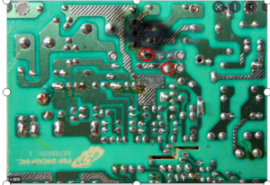
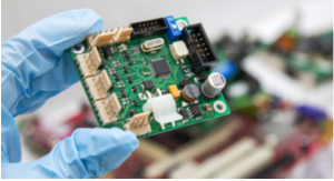
If want to produce a complete PCB board, you need to go through a number of complex processes, When PCB board production process if there are some operational mistake, it will lead to the final production of the finished board quality problems, does not meet the product requirements. Generally common PCB board breakage problem, it will affect the realization of the function of the circuit board.
Causes of pcb board broken line

1, The process of film: film paste the ground is not solid, there are bubbles, if the wet film will also have garbage pollution.
2, Exposure process: the negative due to scratches or garbage caused by the problem, including exposure machine problems, exposure of local inadequacies.
3, The development process: the development of blurred unclear.
4, Etching process: nozzle pressure is too high, etching time is too long.
5, Plating problems: uneven plating or adsorption on the surface when plating.
What causes pcb board line broken , First :look at the form of broken line, Analyzing the form of broken line to find out in which process problems caused by the PCB board broken line problem, and then gradually in the production process may appear to investigate the causes.
PCB board short circuit
This is one of the common failures directly caused by the PCB board can not work, and there are many reasons for this problem, the following we analyze one by one.
(1) The biggest cause of PCB short circuit, is the improper design of the solder pad, At this time you can change the round solder pad to oval, increase the distance between the point and the point to prevent short circuit.
(2) Improper design of PCB parts direction, will also cause the same board short circuit,
can not work. Such as SOIC feet if parallel to the tin wave, it will be easy to cause short-circuit accidents, At this time you can properly modify the direction of the parts, so that it is perpendicular to the tin wave.

There is also a possibility of short-circuit PCB failure, that is, automatic plug-in bent feet. As the IPC stipulates that the length of the line foot in 2mm or less and worry about bending the foot angle is too large when the parts will fall, so it is easy to cause a short circuit, the need to leave the solder joint line more than 2mm.
In addition to the above-mentioned 3 reasons, there are some reasons can also lead to PCB board short-circuit failure, such as the substrate hole is too large, the tin furnace temperature is too low, poor board solderability, solder resist film failure, board contamination, etc., are more common causes of failure, engineers can compare the above reasons and the occurrence of failure one by one to eliminate and check.
PCB open circuit
When the trace is broken, or when the solder material is only on the pad and not on the component leads, open circuit will occur. In this case, there is no adhesion or connection between the component and the PCB. Just like short circuits, these can also occur during production or during soldering and other operations. Vibrating or stretching the board, dropping them or other mechanical deformation factors can damage traces or solder joints. Likewise, chemical or moisture can cause solder or metal parts to wear out, which can lead to broken component leads.
PCB board appears dark and grainy joints
The problem of dark or grainy joints on PCBs is most likely due to contaminated solder and excessive oxides mixed with dissolved tin, resulting in a brittle solder joint structure. Care must be taken not to confuse this with the dark color caused by the use of low tin content solder.
Another reason for this problem is the change in the composition of the solder itself used in the manufacturing process, too much impurity content, the need to add pure tin or replace the solder. Speckled glass from the fiber accumulation layer physical changes, such as separation between the layer and the layer phenomenon. But this situation is not a bad solder joint. The reason is that the substrate is overheated, need to reduce the preheating and soldering temperature or increase the speed of substrate travel.
PCB solder joints become golden yellow
In general, the PCB solder is presented in silver gray, but occasionally there are golden yellow solder joints appear. The main cause of this problem is the temperature is too high, at this time, you just need to adjust the temperature of the tin furnace can be reduced.
Board bad also affected by the environment

Due to the construction of the PCB itself, when in an unfavorable environment, it is easy to cause damage to the PCB board. Extreme temperatures or temperature variation, excessive humidity, high intensity vibration and other conditions are factors that can lead to reduced performance or even scrap of the board. For example, changes in ambient temperature can cause deformation of the board. Therefore will destroy the solder joints, bend the board shape, or will also possibly cause the copper traces on the board to break.
On the other hand, moisture in the air can cause oxidation, corrosion and rusting of metal surfaces, such as exposed copper traces, solder joints, pads and component leads. The accumulation of dirt, dust or debris on the surface of components and boards can also reduce air flow and cooling of components, leading to PCB overheating and performance degradation. Vibration, dropping, hitting or bending the PCB can deform it and cause attendance that cracks, while high currents or overvoltage can cause the PCB to be broken or lead to rapid aging of components and pathways.
Article Source: https://www.pcbsupplier.com/blog/what-is-reason-about-pcb-short-circuit.html
Media Contact
Company Name: SHENZHEN OMNI PCB
Email: Send Email
Country: China
Website: https://www.pcbsupplier.com/